
Beginning Embedded Electronics - 8
Lecture 8 - Eagle: Schematics
We are very proud of this tutorial but it is getting long in the teeth. Be sure to checkout the latest Eagle tutorials over on our learn website:
Here's the original tutorial for your viewing pleasure:
Welcome to the wonderful world of PCB creation! We've used a few software packages over the years (namely Protel DXP) and have found Eagle Layout Editor from CadSoft to be very easy to use, very cost effective, and very powerful.
Eagle is free! There are some limitations in place, but basic students and non-profit groups can use it. Protel is currently about $12,000 a seat.
Eagle is not the 'hobbyists' tool you may think it is. I've seen some very complex 8-layer BGA boards going into a firewall/router consumer product. I too was amazed to hear it was created in Eagle. It can be done, you just need to dream up the device!
There are a few files that you will need to download for this workshop.
-
Download Eagle itself. Currently we use v4.16 (~8MB). Versions are available for Windows, Linux, and Mac. If the above link does not work, google ?eagle pcb download? to get the latest version.
-
Download the SparkFun Eagle Library. This is the collection of all the components SparkFun designs with and therefore components and footprints that have been tested. Unzip and place the SparkFun.lbr file into the Eagle\lbr directory. If the above link does not work, google ?sparkfun eagle library? to get the latest collection.
-
Download the SparkFun Eagle keyboard shortcuts. Place this file in the Eagle\scr directory. If the above link does not work, google ?sparkfun eagle shortcut?.
-
Download the SparkFun CAM file. (Right-click, and choose Save Link As) Place this file in the Eagle\cam directory. This file is responsible for creating the gerber files for submission to a PCB fab house.
Note: The SparkFun Eagle shortcut key script file has an .scr extension. This is a common virus infiltration method. If you choose to download our keyboard shortcuts, and you don't trust us, rename the file to a .txt extension and view it in a text viewer. There's nothing there but text and Eagle commands. Just be sure to rename the file to the .scr extension so that Eagle will use it.
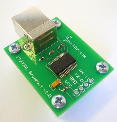
To learn how to use Eagle, we are going to create a simple breakout board for a popular USB IC. The FT232RL is a USB to TTL serial converter.
What is a USB to TTL converter?
Once the FT232RL is attached to the USB port on your computer, you will need to install some simple drivers (available for Windows, Linux, Mac), and then you will see a Virtual Com Port (VCP) appear on your computer. You can then use hyperterminal to open this new com port number. Any letters that are typed in hyperterminal are converted to a USB packet in the background, sent down the USB cable to the FT232RL where it reconstructs the serial information and passes these letters out the TX pin on the IC at whatever baud rate you choose. If you have a device connected to this TX pin, it will hear the serial letter and react. This will effectively give your device USB connectivity and you won't need to know a thing about how USB actually works!
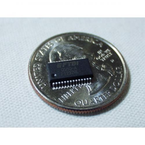
This IC is very popular, but only comes in surface mount device (SMD) packages (sound familiar?). So let's spin a simple PCB that will allow us to use this handy IC.
When in doubt, follow the manufacturer's recommended circuit. This 'typical' application is just what we need.
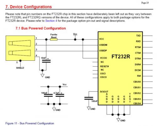
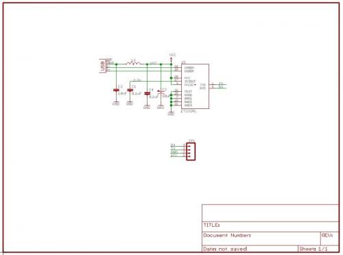
This is a bare-minimum feature setup for the FT232R. Just what we need for simple TX/RX to USB. We want to plug the FT232RL on to the USB port, have it bus powered, and possibly power the rest of our circuit. Our ATmega8 uses 5V so we'll tie VCCIO to the USB 5V. A USB connector, a couple 0.1uF caps, a bigger tantalum cap, a ferrite bead, this doesn't look so bad!
Before we can get started, we need to create or locate a library part for the FT232RL. I really don't like using other people's footprints and schematic parts but in this case, FTDI has created some free libraries for their parts. This page should have the Eagle library (search the page for FT232RL) but if not, google 'ft232rl eagle footprint'. We also have this part proven in the SparkFun.lbr library. Use their library, use ours, create your own, it doesn't matter. But because we are most comfortable with our own parts (we know they work!) we will be using the SparkFun.lbr file for this tutorial.
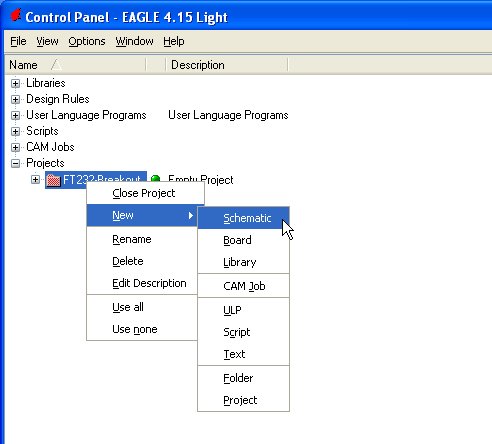
Now let's add the FT232RL part to our schematic. Close the library editor and go back to the Eagle Control Panel. Click on File->New->Project. Name this new project 'FT232-Breakout'. Right click on the FT232-Breakout project and create a new Schematic:
The schematic editor should open. Now go back to the Eagle Control Panel and expand the SparkFun Library:
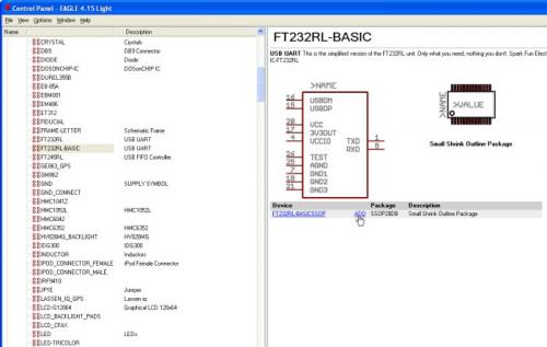
You should see a long list of parts. Highlight the FT232RL-Basic part and in the right screen click on ADD. The schematic editor will pop up allowing you to place the FT232RL.
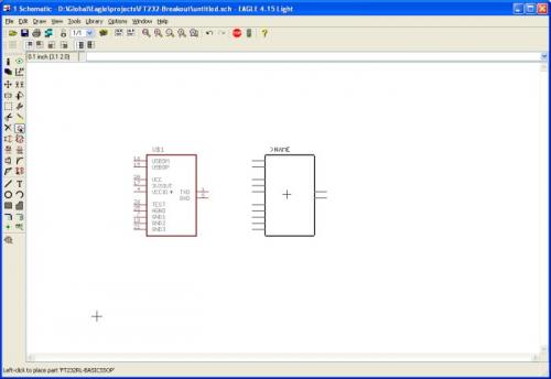
Now save your schematic!
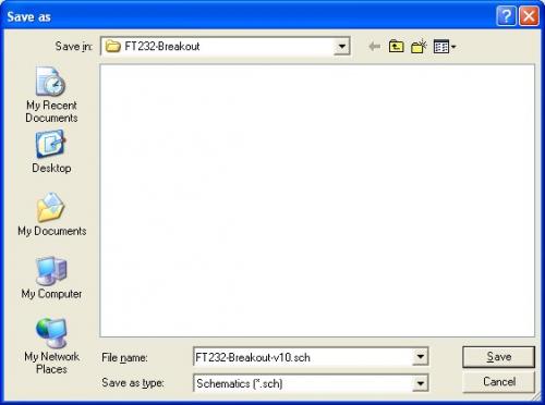
I like to use a board name and a version number within the file name. -v10, -v11, v12, etc as 1.0, 1.1, and 1.2 advance through layout changes.
Now add these other items to your schematic:
-
1 x FRAME-LETTER : This will add a nice frame to your schematic. Add all parts inside this frame.
-
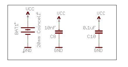
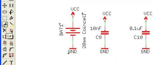
3 x CAP (Device name CAP0603) : 0.1uF/0.01uF 0603 capacitors
-
1 x CAP_POL (Device name CAP_POL1206) : 10uF tantalum capacitor
-
1 x INDUCTOR (Device name INDUCTOR0603) : Ferrite bead
-
4 x STAND-OFF( Device name STAND-OFF): This part will add a hole and a keepout ring for a #4-40 screw. These can be used to raise your board up off a surface or to mount your board to an enclosure.
-
USB (Device name USBPTH) : USB Type B through-hole connector
-
M04 (Device name M04PTH) : Four pin 0.1" connector
-
GND (Device name GND) : Ground connections
-
VCC (Device name VCC) : Power connections
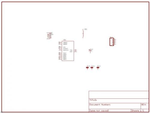
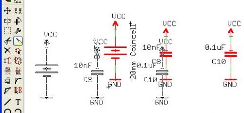
Parts added to the schematic
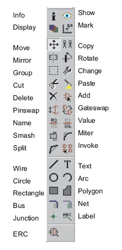
You can click on the button you need on the menu on the left side of the screen. You can also hover over each button and its name will pop up. This works great for beginners but as you advance, you'll want to speed up layout by using keyboard shortcuts. Here are some of the basic quick keys:
-
Press escape at any time to stop the current action and return to the schematic window
-
F7 to move a part
-
Alt+F7 to group a bunch together
-
F3 to delete a part
-
F4 to rename a part (change C7 to C2)
-
F5 to re-value a part (change 0.1uF to 10uF, etc)
-
F6 to smash a part (be able to move the name and value tags)
-
F9 to start a wire
-
Alt+F9 to add a label to a wire
NEVER change the grid size in the schematic editor. Leave it on 0.1inch steps and don't use the alternate 0.01 step. If you do, you won't be able to hook wires to the pin tie points.
Now we just need to begin wiring nets. Arrange the pieces so that there is as little net overlaps as possible.
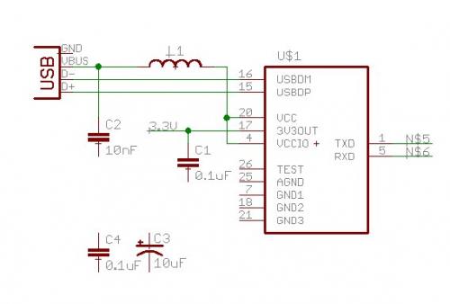
Primordial FT232RL breakout
To wire a pin (TXD) to a far point (the 4-pin connector for example), instead of sending a wire half way across the page, we use net names. The green wire is not physically seen on the schematic, but Eagle knows to connect the two points on the layout because the two green wires have the same name.
Press F9 and click on pin 1 (TXD). Bring out the net a couple square widths and left click again to end the net. Press Alt+F9 to name the net. Click on the wire you just created. You should see a net name (like N$5) appear and be floating. Anchor it to the wire and TX pin:
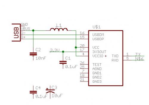
To change the name on the N$5 wire, press F4 (Name command) and click on N$5. A window will appear - type 'TX' and press return. The TX pin should be correctly labeled and we have a few of the schematic connections.
To rename a device (change U$1 to U1), press F4 and then click on the device you want to rename. This also works to rename a net.
To change the value of a component (0.1uF to 10uF) press F5 and click on the device you want to change the value of. To move a device, press F7 (move command) and click on the device you wish to move. Now with a little renaming and rearranging the various components:
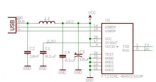
We've thrown a 4-pin connector into the schematic and used a very stripped down schematic symbol for the FT232R. For the purposes of this tutorial, we really only care about VCC/GND/TX/RX - the bare minimum. If you need access to more of the pins, use the more complete FT232R symbol and break them out!
Use the mirror command and rename the 4-pin connector (press F4 to rename a device):
I probably could have wired JP1 directly to the various pins but I wanted to demonstrate the net/name properties. This will also make it easier to label the pins on the PCB. Speaking of which, if you have not already, click on the 'Board' button to open the PCB editor:
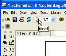
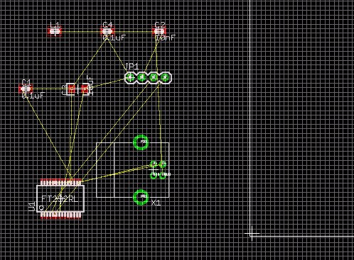
All right! We've got the components onto a board and most of the nets connected, time for PCB layout!
How to copy and paste in Eagle Schematic:
This is perhaps the most counter intuitive part of Eagle. As with any new technical software, it's like learning a new language. Once you know the intricacies, you'll love it.
To copy one thing within a schematic is reasonably simple. Click on the 'Copy' button, then click on the thing you want to copy and that thing (component, wire, net name) will be duplicated and floating under your cursor. Drop it wherever you want it.
To copy a group of stuff within a schematic is completely wacky. First click on the group command:
You are going to create a frame around the stuff you want to group together. Left click and hold on one corner. Drag to the opposite corner. Now release the mouse button. The items that are part of the group should now be highlighted like this:
Now click on the Cut button. I know you don't want to delete these items - this is just how it works. Click on cut, move your mouse cursor to the middle of the group, and left click. Nothing happened right? That's okay. The group of items has been copied to the buffer. Now click on the paste button:
You should now have a copy of the group of items floating around. Drop these items wherever you need them in the schematic, or hit escape to return to the schematic window. I know, very odd but this type of group/modify steps comes in very handy over time.
We love feedback! Please report typos, comments, or recommendations to spark@sparkfun.com.
Lecture 1 - Background and Power Supply
Lecture 2 - How to Get Code Onto a Microcontroller
Lecture 3 - What is an oscillator?
Lecture 4 - UART and Serial Communication
Lecture 5 - AVR GCC Compiling
Lecture 6 - Soldering Basics
Lecture 7 - SMD Soldering
Lecture 8 - Eagle: Schematics
Lecture 9 - Eagle: PCB Layout
Lecture 10 - Eagle: Creating a new part
Common Mistakes, Tips and Tricks
I agree, a parts list would be helpful.
What about a parts list particularly what type of connector. There are so many at digikey.
Having a tough time following the section where the tutorial tells you to "add these parts." I cannot locate the #3 x CAP (Device name CAP0603) : 0.1uF/0.01uF 0603 capacitors, 1 x CAP_POL (Device name CAP_POL1206) : 10uF tantalum capacitor, 1 x INDUCTOR (Device name INDUCTOR0603) : Ferrite bead or the USB ((Device name USBPTH) : USB Type B through-hole connector).
Any advice?
Is there any way i can use a 2-pin tactile push button on a pcb? Should I prefer a 2 layer pcb for the above or a single layer pcb would suffice?
I can't find the shortcuts file. The link http://www.opencircuits.com/SFE_Eagle_Shortcuts goes to "Open Circuits has a problem". Googling ?sparkfun eagle shortcut? doesn't turn up anything that looks likely. I see this tutorial is rather old. Should I be using another?
Kamiquasi is right on the GitHub link. We are also working on porting this material over to our learn site with new tutorials, so you might want to check these out. Eagle Schematics and Eagle Board Layout.
Looks like the original file is actually hosted right here at sparkfun.com. However, I suspect that going forward you might want to stay up-to-date on the file through the SparkFun Git repository version. If you go up one level to SparkFun Eagle Settings you should find a convenient 'Download ZIP' button that will let you download all of SparkFun's Eagle-related things outside of the component libraries.
Eagle 6.4.0 Light was crashing repeatedly on my Win'7 64-bit machine. I emailed Cadsoft tech support and they provided me with this fix:
If you go to where the Eagle executable is (\Program Files (x86)\Eagle-5.11.0\bin) and right click on the Eagle program, you can select Properties.
Under Properties, select Compatibility. On that screen, check two boxes:
Compatibility Mode->Run this program in compatibility mode for Windows XP SP3 Privilege Level –> Run this program as an administrator
Eagle hasn't crashed since I implemented this fix.
I feel like I'm missing something. I downloaded the library, and put it into the Eagle/lbr folder and I can see it listed, but its not just one library, its a whole bunch, and they don't seem to have the FT232RL component.
I'm thinking this tutorial is a tad out of date. Am I wrong?
It is a tad outdated, however you can still find the FT232RL in:
Library: SparkFun-DigitalIC.lbr
Device: FT232RL-BASICSSOP or FT232RLSSOP
You'll have to be in your Schematic to add this part - if you try to add it on the board, you won't find it since that pools from the footprints (footprint used is SSOP28DB).
I downloaded the Eagle 6.4 sparkfun libraries (again), find the "STAND-OFF" mentioned in the tutorial yet right click "add to board" is greyed out. I have no way of using anything in that library.
A wild-card search of "SparkFun*" gets me only 4 items available:
BREADBOARDMINI WIZ811MJ WS100 WS2801
Note: other libraries supplied with Eagle do not have this issue.
Update: I can get it to work if I copy the items in the Sparkfun library subdirectory to the eagle \lbr directory. Evidently I cannot leave them in the Sparkfun subdir under \lbr
In the Eagle main window, go to Options / Directories. The "Libraries" field defines where Eagle will look for parts libraries. You can add multiple directories (for example adding wherever you've placed your SparkFun libraries) by separating them with semicolons. Here's mine:
Restart Eagle and you should be able to use all the libraries.
BONUS TIP: To disable libraries, click on the green dot by the filename to turn it on and off, or right-click on the parent folder and choose "use all" or "use none". Very handy!
I find it impossible to locate INDUCTOR0603 (let alone the previously mentioned CAP_POL1206, though for it I did manage to find something similar). I even tried the suggestions earlier about using INDUCTOR* (wildcard found some hits but only wrong SMT devices) or INDUCTOR06* (which sent my very high end PC off on a very long search to no avail). Whats the secret here? just pick random inductors and assume their tutorial is way out of date? I'm on Eagle 6.4
This is disturbing. I am trying out Eagle version 6.4.0 and it has crashed twice in less than 1 hour, losing unsaved changes. Is it typical to have to manually save changes after every few edits to avoid this? Have I downloaded a buggy beta version? This is not behavior I expect from a serious product.
You're right, that's not good. We're still on 6.3 and earlier (6.4 is brand new) and haven't had such issues. Definitely let Cadsoft know about the bugs you're seeing; they tend to be very responsive to such problems. It also appears that 6.3 is still available on their beta download page so you may want to downgrade until the problems are solved.
Hi everyone, can you please tell me where exactly i can download the library in the link : https://github.com/sparkfun/SparkFun-Eagle-Libraries/blob/master/SparkFun-LED.lbr ?? all i can find is a code.
thanks
The easiest thing to do is probably to go one level up: https://github.com/sparkfun/SparkFun-Eagle-Libraries and click the "ZIP" button to download a zip file containing all the SparkFun libraries. Put them in your Eagle lbr folder (or add a new directory to the options/directories menu), restart, and the libraries will be available for your use.
Maybe I'm missing something, but shouldn't the ground pin on the USB connector be connected to the GND net? I wondered about it in the tutorial, and when I downloaded the SparkFun version of the Eagle files, sure enough it isn't routed from the connector on the board layout.
I'm probably in reality a stumbling, bumbling idiot- But how exactly does one download the Eagle part libraries so that they wind up in my computer in a format that Eagle understands? I tried the usual methods, but only got webpages. I could not see a "download" button anywhere. Github sucks.
Click the "ZIP" button
SparkFun Eagle Library. link above states "GitHub page not found" i tried googling "?sparkfun eagle library?" to be sent to the same invalid link
Sorry about that! The new link for our Eagle V6+ libraries is: https://github.com/sparkfun/SparkFun-Eagle-Libraries. The old Eagle V5- libraries are at: https://github.com/sparkfun/Old-SparkFun-Eagle-Library.
how to add information in the frame letter?
If you want to add permanently non-changing information to the frame, you may want to edit the part in the library. If you just want to add your name etc. to your schematic, just create some text and manually paste it in the appropriate spot.
I cannot open any SparkFun Libraries in Eagle 6.1.0. When I attempt to open them I get Error line5, column 6: This is not an EAGLE file
Any suggestions?
Download them as a zip file, and unzip in the eagle library folder.
No worries...
It seems like there is a little quirk with Eagle (5.5.0 Freeware). If I place a few pieces on my schematic, then click the board button to set up my board, and then realize I need more pieces the board doesn't update.
Example:
Add USB and FT323RL and connect them
Then Click the Board button to set them up and realize I forgot capacitors
Go back to my schematic, add the capacitors and connect everything up if I click the board button, the new capacitors don't show up.
Any help with this? Thank you.
While going through this tutorial, I was able to add parts using the Sparkfun library until I reached Stand Off. When I opened up Stand Off there was not an add button. I tried to do a copy and paste which did not work either.
I am using Eagle 5.11.0 Windows version. Has anyone else run into this problem? and/or know of a fix?
Also be sure you're using the latest SFE library; we now keep it on Github here: https://github.com/sparkfun/SparkFun-Eagle-Library
Type the following commands into the Eagle schematic command line:
Got it to work.
Thanks for the commands.
I just downloaded and installed Eagle 5.11.0 Light. I ran through this tutorial just fine, except when I got to the end my nets didn't show up in PCB editor. I went back and deleted them, and recreated them. Used the Net tool to bring the green line out from the chip and from the connectors a few squares, right click on it, named it, right click again and labelled it (with the floating label per tutorial), but they are not connecting in my layout window. I check their properties and they are on the same nets (even asking me to confirm I am adding them to an existing net), but not showing connected in my board layout. All my caps are tied together (presumably to GND), so something is working. Any suggestions?
The images in the Eagle tutorials seem to be broken ... can the images be restored?
To get the images working on this page, run the following Javascript by copying and pasting it into your URL bar:
javascript:(function(){for(var img=0;img < document.getElementsByTagName('img').length;img++){var imgEle = document.getElementsByTagName('img')[img]; if(imgEle.src.indexOf('tutorials') != -1){imgEle.src = imgEle.src.substring(0,24)+ imgEle.src.substring(33);}}})()
That should make the images show up.
Thank you 'Joshie', it did not work with chrome, but it works fine with IE. Once again thanks a million.
PS. tryed again and it worked fine in both, manu thanks.
Andy
http://www.sparkfun.com/commerce/images/tutorials/BeginningEmbedded/8-EagleSchematics/Eagle-LayoutMenu6.jpg
overrun "commerce" in the image links.
Please correct
Great tutorial. I wonder what happened to the images, it does not display. I've tried IE and Chrome but the images still does not show!! It is a bit difficult to follow the tutorial without the images though. I wonder if they are removed. any comments are welcomed.
Great!
ALT-F9 turns out to be a Gnome shortcut to minimize the current window. due to this the Alt-f9 key minimizes the window instead of adding a label to a wire. How do I work around this? could someone at swparkfun try working this tutorial on a non-windows platform to find issues such as this?
I use "SparkFun-2007-06-06.lbr".
When "FT232RL-Basic" is added, the "VALUE" of the device is not displayed. In the final schematic as shown in the tutorial above, the device's "VALUE" is shown as "FT232RL-BASICSSOP". How can I display the device's "VALUE"?
Thanks.
I've done designs from scratch without difficulty thanks to your tutorials but am working on some designs that are not just slightly more complex. One design doesn't get passed 50.8% autorouted and then it looks like garbage so I want to hand route it.
You have no tutorial to even start this subject and BatchPCB (where I get my boards done) sends me back here. Laying out using your tutorials then means my traces are 0.1" aligned so cannot touch almost all of my traces.
Help is greatly desired or at least a web link to somewhere I can get more info. Thanks
That happens a lot.
1. Click the "Ripup routed tracks" button (Next to the route manually button)
2. Go to the toolstrip at the top and click on the green stop light (Go).
3. You need to align your parts better. Square shaped surface mount chips are hard to work with, especially for beginners, so try replacing surface mount parts with pth (through hole) parts.
4. Try spacing out your parts more, that often helps
5. Also remember to leave some space around the edges of the board to allow traces to run on the sides of the board.
Re: working with Groups. CTRL+Rightclick doesn't work on a Mac, instead use the 'Command' key on your keyboard. (I'm using Eagle v5.11.0)
Great tutorial BTW, thanks, easy to follow. :)
Loved this, very easy to follow along with
Just a comment about copy/paste and using tools in general...
(I haven't been using Eagle long, but the following does seem to hold true for most tools - might be new to version 5)
To act on a group of objects, use CTRL+Right-Click.
1) First use the Group tool to select a group of objects.
2) Next, select the tool you want to use, such as move, copy, etc.
3) Finally, hold the CTRL key and Right-Click any object in the group to use the tool on all objects in the group.
If you have a tool selected, then switch to the Group tool and select some objects, you can immediately CTRL+Right-Click to use the last selected tool on the group, without switching back from the toolbar.
If you use CTRL+Right-Click, it makes working with groups of items much more intuitive.
Just a heads up to the sparkies out there that are running Eagle on Ubuntu. You must be running a version >= 4.6 to use the latest SFE footprint library. I was running Eagle ver. 4.16r2 and was informed that I needed at least 4.6 when I tried to load the file unzipped from this github file: sparkfun-SparkFun-Eagle-Library-be2093b.tar.gz I went ahead and downloaded the latest Eagle install script and after a bit of wrangling to get the Application menu squared away, I'm now running Eagle ver. 5.10.0 with the latest SFE parts footprints.
...I had to USE the sparkfun lib.
What lib is the STAND-OFF device in, I do a search, but can't find it...
Put asterisks around your search like this:
* STAND-OFF *
Also, check all three category boxes.
For those of you having trouble finding parts in the libraries - you're probably searching the hundreds of libraries that come with eagle.
Download the and use sparkfun library, all the parts above are in it. You have to restart eagle to get it to see new libraries. Ignore (for now) the other libraries.
i cannot get the cam file to download, it just opens in firefox, google chrome, and internet explorer on my computer. can you please fix or tell me what im dooing wrong?
Right-click on the .cam file link and selecting "Save Link As...", instead of just clicking on the link.
Great tutorial, just making my way through it again with Eagle :)
Just noticed that on opencircuits it states that the library file can be used for commercial purposes but when using it in Eagle it states in bold text that it is not to be used for commercial purposes?
I was looking into moving items around and found this note which seems to work better than the instructions above.
"When you want to move them to a new location press F7 and then use the Right mouse button to drag them to a new location. Usually left mouse button is used for individual objects and right mouse button for groups."
--http://www.smishra.com/notes/eagleCAD_Tips.html
P.S. THANK YOU for this tutorial! It really got me off to a great start! I'm 21, been doing electronics forever and am about to do my Senior Design project. Thanks a bunch!
(Clarification: I'm using Eagle Light version 5.5.0) as freeware.
Having a tough time following the section where the tutorial tells you to "add these parts." I cannot locate the #3 x CAP (Device name CAP0603) : 0.1uF/0.01uF 0603 capacitors, 1 x CAP_POL (Device name CAP_POL1206) : 10uF tantalum capacitor, 1 x INDUCTOR (Device name INDUCTOR0603) : Ferrite bead or the USB ((Device name USBPTH) : USB Type B through-hole connector).
Any advice?
Also, don't search for whole part names. Only search for segments of the name.
For example,
CAPinstead ofCAP0603.Even I'm using the freeware version. I can see CAP0603 but I can't add it into the schematic. The buttons on the menu are disabled. Any ideas! :(
Post a screenshot.
So apparently, I can click the add on the left toolbar in the schematic editor and it give me dialog to search for parts.
I search for CAP0603 and I got it :)
Fantastic. If you're working on a design and need some design review, feel free to stop by the IRC channel. People there are always willing to help.
Here's a hint, to make searching for parts easier in Eagle, put it inside wildcards, eg: *INDUCTOR*
Great job as always! Thanks for the Eagle basics.
Are the Eagle tutorials available in PDF format? I find it difficult trying to bounce back and forth between the tutorial and the EagleCAD software. It would be nice if I could print out a copy of the tutorial and leave the Eagle software on the screen without having to change software focus.
Tnx and great work. I have a project in mind and would like to use ur tutorials to begin my learning process.
Rob K4UD
If you used linux you can have say 4 desktops (as many as you want) and open a browser or whatever in each.you just switch between pages as required . Windows has a similar system
If you install a pdf printer, you can convert anything you could otherwise print to pdf. Here is a good one: http://www.cutepdf.com/products/cutepdf/Writer.asp
I use it as a default printer and only after I have verified that everything looks as intended to I send it to the physical printer. I find that I actually wastes less time this way, cause I'm not waiting for the wrong printout to print. It saves ink/toner and paper as well.